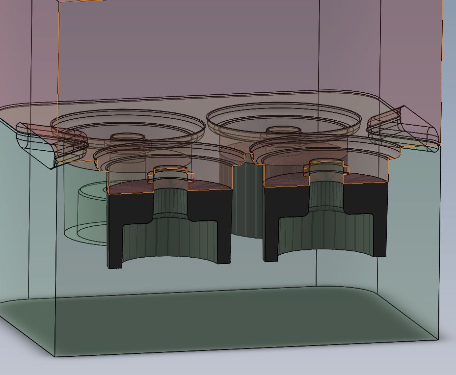
So I’ll start off with the fun stuff, above are three photos The first a slice of a mold I am making.
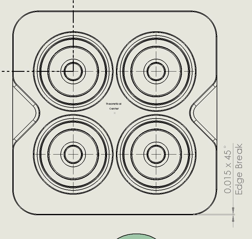
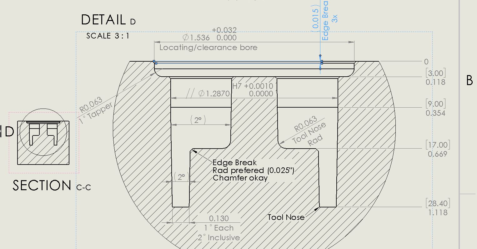
The second and third are prints of them.
I’m looking for feed back on how to tolerance the prints properly, or at least best practices. Currently I am trying to figure out the locational tolerances of the mold pattern in a top down view.
I feel like the stepped diameters are rather sorted? The Dia is ~32mm +0.001" on the pocket, and -0.001" on the plug. The radied stepped is just clearance with -0 to+1/32 on the pocket,and +0 to -1/32 on the bore again. Everything after that is strictly part geometry rather than mold geometry.