Composites Engineering

In this thread I will outline the basics of composites engineering. If you are unfamiliar with material science I suggest you read engineering basics first. If you do have an understanding of material properties then continue on.

Lesson Plan

  1. Introduction to Composites
  2. Micromechanics
  3. Macromechanics of a lamina
  4. Macromechanics of a laminate

This section is quite a bit more complicated and it’s going to take me more time to put up each examples. Keep checking back for updates

So what are composites? Contrary to what most people think they’re not just stuff that planes and racecars are made of. They’re not not just carbon fiber. Composites are in fact a whole different class of materials, with thousands, if not millions of different types. To put it simply composites are materials made of two or more materials. The most well known type of composite is fiber reinforced polymer composites i.e carbon fiber epoxy, fiberglass polyester etc. However other common but overlooked composites are wood (cellulose and lignin) and steel reinforced concrete.

To put it bluntly composites are awesome because they can engineered and designed in any which way a creative person can imagine. Take plastic for instance, it’s pretty weak and can’t really support much on it’s own. But add some stiff fibers to it and now it’s able to support the load of an aircraft. Another example, and one of the first for composites, is mud hut construction in Ancient Egypt. If you were living back then you’d have to make your house out of brittle rivermud bricks. IF the bricked survive transport they would probably break when constructed into a house. But the resourceful Jews back then realized that if they added hay to their bricks they would hold much better. We now know that the hay fibers held the bricks together in tension and the rivermud held the house together when in compression.

You might asking yourself, “If composites are so useful why don’t we make everything out of them?” Well if you’re on this forum you already know that composites are expensive. They’re expensive to make, they’re expensive to design, and they’re expensive to research. Composites just don’t have the years of research and theory that more commonly used materials like metal and plastic do. Attempting to manufacture a new one takes years of R&D, labor and skill and while the cost is negligible for some industries, at the moment it’s still too expensive to replace traditional materials

So in the realm of composites the most prominent and popular by far are fiber reinforced polymer composites. You know these are fiberglass, carbon fiber and polymer Kevlar. In layman’s term the name means plastic that has been strengthened by adding fibers.

If you’re studying these composites there’s actually two routes you can take. Some engineers, chemical mostly, study the fiber and matrix at microscopic level. They spend their time doing tests on the fiber bonds, resin structure, and on each individual material.

Or if you’re like me you’re more into the macromechanics, that is regular world behavior. Engineer’s studying at this scale are interested in how the whole composite performs, how a structure behaves, the fatigue strength of a composite etc. These engineers are usually mechanical.

Either way though it’s important to know a little bit of both so you can get a full picture of what’s happening. In the next round of posts I’m going to walk you through micromechanics first, then macromechanics. The material is a bit harder and requires some understanding of matrix operations. If you need help please feel free to post them in engineering talk! Like the last thread this one will stay closed so it’s easily readable.

Here’s some terminology you need know.

Fiber - Easy enough, it’s whatever fiber we’re dealing with at the moment

Matrix - This is what the fibers are in, most of the time it’s epoxy but there’s also polyester and vinylester. If we jump out of the polymer mindset for the second we can also include metal and ceramics.

Fiber Direction - Pretty self explanatory, the direction the fibers are running. In every calculation from now on out the fiber direction is always one.

Volume Fraction - The percent of fiber in a composites. 1.0 is pure fiber, 0.0 is pure matrix, .5 is half fiber half matrix

So if you’re here you should already understand the concepts and applications of Young’s modulus (stiffness), Modulus of Rigidity (shear stiffness), and Poisson’s ratio (Strain ratio)

This lesson will be taught at face value only This means I will present the material with the assumption you know the underlying material, such as the terms above. If there is enough demand I will go into topics that are not well understood in more detail but there simply is too much of it for me to write it all up right now. Literally entire textbooks and semesters of material. I will do my best to make the material accessible though starting with a full explanation of the coordinate system.

Coordinate Plane
cube.jpg
This is the coordinate system I will use. The fiber direction is 1, perpendicular to the fiber is 2. The other direction, out of the plane of fibers is 3. I will exclusively be using the 12 direction.

Fiber Plane
12plane.png
This is the sketch of the 12 plane. We will be calculating the material properties of the composite for loading in this plane loading. Why not out of plate loading you ask. Because I haven’t learned it yet, it’s gonna take me a few more classes and an acceptance to a masters level course to get there. As it stands I had to take the highest level undergraduate course and waive two prerequisites (no easy task) just to learn this much!

So a few things, stress in the fiber direction will be known as σ11. Stress in the two direction will be known as σ22

Shear Loading
shear2.jpg
Shear is a bit trickier. It’ll be known as τ12.
This means deformation in the one direction caused by a stress in the 2 direction. For your reference though another common nomenclature for shear is σ6. This is because shear is referred to by 9 - the numbers of the plane defining it. So in this case its 9 - 2 - 1 which is 6. Some books the former name, others use the latter. It’s confusing I know. You just have to learn both

I hope you’re ready for some formula’s because this will be the first post to include them.

Before we start I need you to understand a few things
We are using a strength of materials approach to this model composites. This method works fine for nice simple shapes and loading conditions. However once you start throwing weird geometries and loads these fail at accurately modeling the material behavior.
The formula’s posted here are theoretically derived. Important word is theoretically. Composites have this nasty habit of not following the theory very well. I will post some experimentally derived equations but experiments can only be run on a very narrow selection of materials and conditions so their increased accuracy is limited.
All the composites will be created from unidirectional lamina. The mechanics of woven cloth are harder to predict experimentally and research is still being done to better understand the mechanics and behavior of composites created with bidirectional lamina. A better reason is that I haven’t learned it yet so I can’t teach it to you.

With that let’s get going.

Formula 1 - Volume Fraction
volume fraction.png
Volume Fiber over total volume. It can’t get any easier. This is one of the most important predictors of composite behavior since it tells you how much of each substance is in here, not accounting for voids. The theoretical maximum is .72 or 72 percent fiber. In most cases the higher the better.

Average Density
density.png
This next formula is pretty simple too. Take the density of the fiber and multiply it by the volume fraction fiber, do the same thing to the matrix and add them together. That’s your average density. One important thing to note though is that you can put volume fraction matrix in terms of volume fraction fiber. This makes calculations a bit cleaner since there’s less numbers to work it. Everywhere you see 1-vf you can think Volume matrix and you’ll be just as correct. The formula’s format is commonly known as the rule of mixtures. Mix x of this and y of that and you get something in between defined by a linear relationship.

Stiffness in Fiber Direction
e1.png
This formula gives you the stiffness in the fiber direction. This is indicated by the one subscript. It’s important to label terms like these because as you’ll soon see there’s another stiffness for the two direction. The formula itself is pretty basic. Another application of the rule of mixtures

Poisson’s Ratio
nu.png
By now you know how this works. Take each one, multiply by the volume fraction and you’re done.

The next set of equations follows another format.

Stiffness In 2 Direction
e2.png
This is the theoretical stiffness when pulling along the fiber width. Notice how the matrix, with a low modulus, dominates the equation while the fibers, with a high modulus, play a lesser part.

Modulus of Rigidity
g.png
Similar to the previous stiffness. One good thing is that the shear is the same on the 12 plane when applied perpendicular and parallel to the fibers.

All of these formula’s are derived theoretically using variables. No numbers needed, but here’s a few caveats. The formula’s in the previous post are all pretty accurate. However the formula’s in this post are not, they’re actually pretty far off from the real world behavior. Can you spot why? Don’t scroll down if you want to figure it out yourself.

Here’s the answer. The first one’s are fiber dominated, meaning the bulk of their final value is determined by the properties of the fiber. The ones below are matrix dominated, meaning the most of the final number reflects the properties of the matrix.

One reason for this is that we missed an important parameter in these equations, which is the bond strength of the fiber and matrix. It turns out that in many cases the fiber and matrix separate and act independently. It’s not a big deal when you’re pulling in the fiber direction because they’re both still being pulled equally. But if you pull in the two direction, once the bond fails the composite will just crack in two. I’ll use a rubber band analogy since they seem to work so well. Glue two rubber bands together lightly with Elmer’s glue along the length. If you pull along the length both pull back even if the glue fails. If you pull each one separately though once the glue fails they’ll just fly apart. Bond failure is one of the biggest problems in composite applications and it’s also annoyingly one of the hardest to predict and account for.

Above are the four parameters you need to calculate the elastic response of a composite material. I left out a few things like thermal expansion and failure stresses in the interest of time but I will complete those sections if there is a demand for them. If you’re interested let me know. Otherwise continue into lamina macromechanics!

With the four values shown above, young’s moduli, shear modulus, poisson’s ratio, it is now possible to calculate the reactions to in plane loads. This section requires a grasp of matrix algebra, I will try and take it slow but you may need to review your matrix multiplication rules.

This next section will be pretty difficult to understand going forward but I will present it this way since it’ll make the most sense later. I HIGHLY suggest that you skim this section the first time, read forward a bit, and then come back and reread this when you feel comfortable.

General Compliance Matrix
General Formula.png
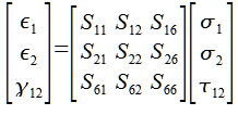
This is the general form for the compliance matrix. It is called the compliance matrix because it shows how much the material complies, or deforms, under a load. The stress values on the right are multiplied by the compliance matrix to show the strains on the right. The values on the left of the equal sign are strains, the sigma’s and tau on the far right are stresses. It is important to note that those two are environmental variables. The values that describe the composites are all the variables in the S matrix, or the center one with all the S’s.
You can see that 9 variables are needed to fully describe the composite in this case

Uncoupled Compliance Matrix
orthotropic.png
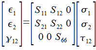
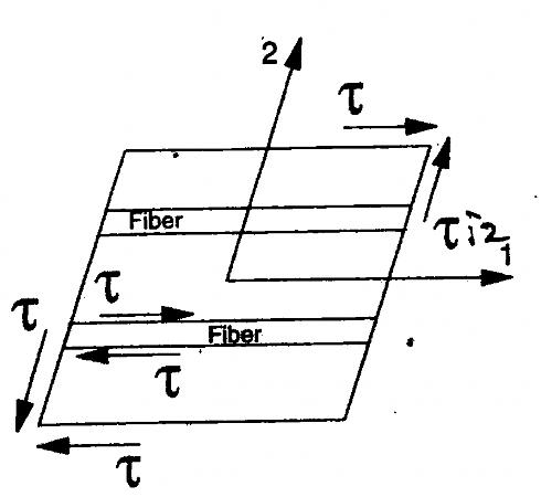
When a fiber reinforced composite is loaded in the fiber direction you lose the shear coupling terms. Every value that coupled the shear stress with a linear strain is now zeroed out.
With the removal of the coupling terms you can see that 5 variables are needed to describe the composite

Reduced Compliance Matrix
completedmatrix.png
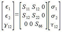
By exploiting one last relationship we can remove one more variable. The more subtle change this time is S12 and S21. By doing some math it has been shown that these two are equal. If you’re feeling brave you may verify this by using the work energy theorem. In general with in plane loading of composites the following relationship holds.
equailties.png

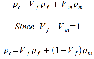
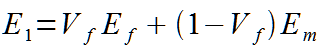
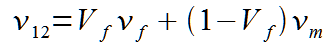
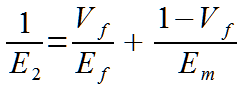
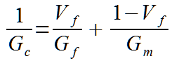
So with the reduced matrix above it only takes 4 variables to describe the in plane loading of a unidirectional composite material. Thankfully the calculation of those variables is quite simple.

values.png

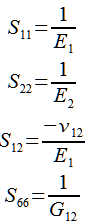
These formula’s are actually the same ones we saw in the materials engineering thread, the only difference here is the lack of stress. However as you’ll soon see these terms combine with the stress terms to produce identical equations to the loading we described before. I don’t expect all of you to see this instantly so in the next post I will go step by step in explaining how all these variables come together.