Glassing to aluminum. Etching?

Hey guys. First CF project i’m working on. Gonna be an intake plenum for my Nissan RB20. It will see at the most 20lbs of boost. I think i have everything worked out i just have a question about the first layer of glass which will attach directly to the aluminum base plate.

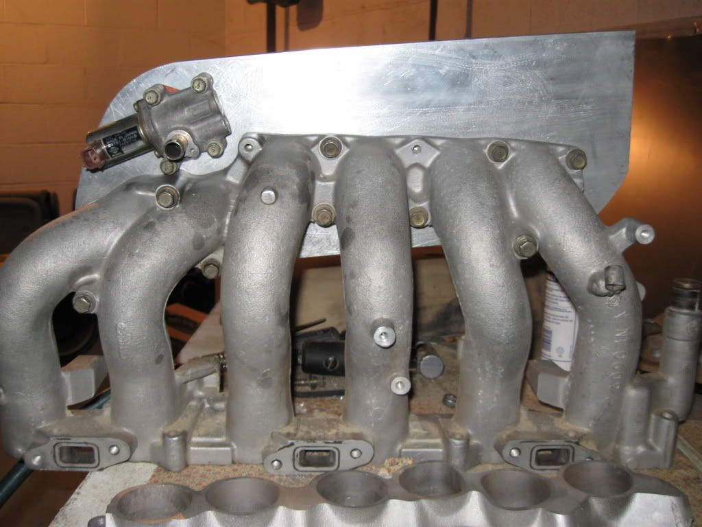
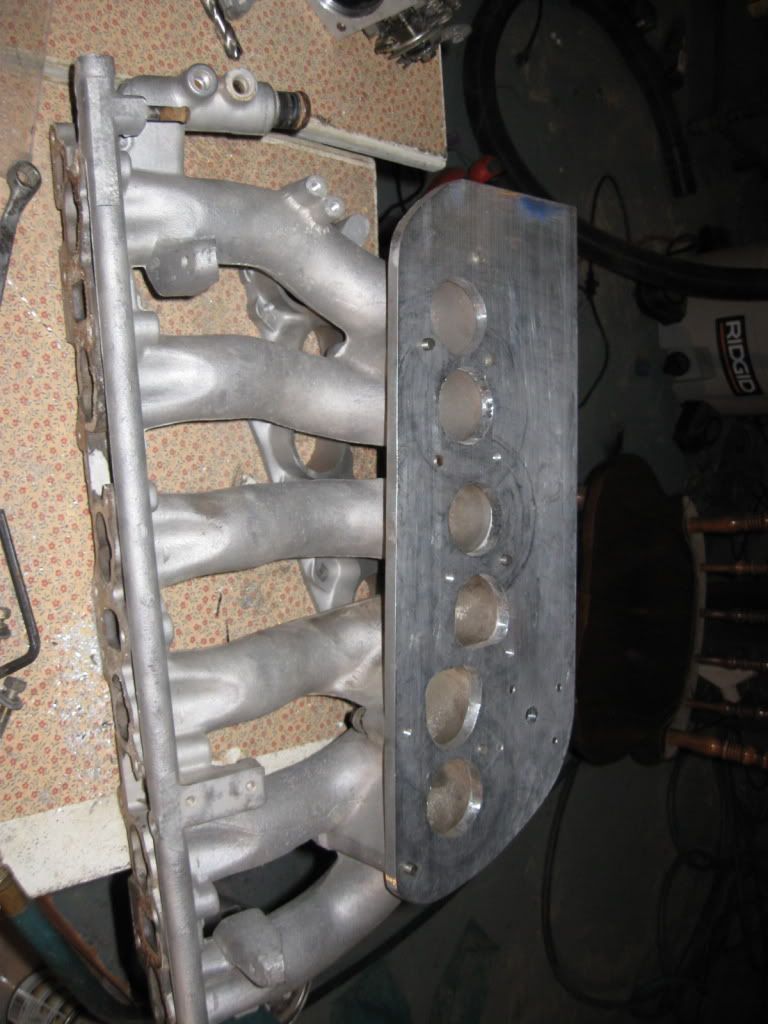
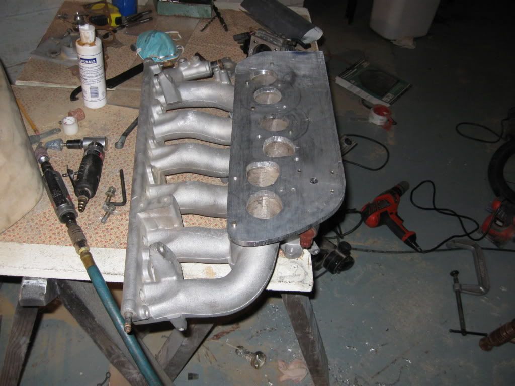
Here is the base plate i machined bolted to the lower intake runners.


Here is the original mold i made out of wood.

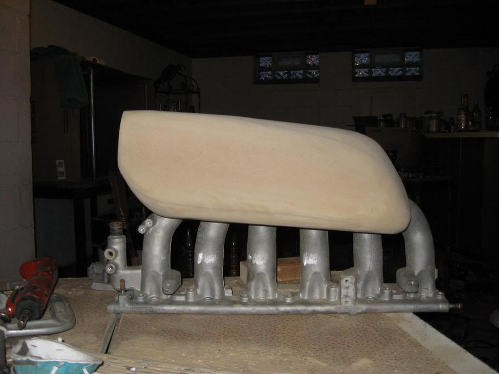
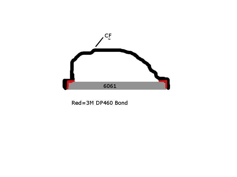
I was going to try and form some aluminum on this but that wasn’t working out too well. I will be making a new mold out of foam. The foam mold will be a little bit inset around the edges of the baseplate and i will wrap the glass/CF around the edge of the baseplate kind of like this [-----] ([) being the glass and (-) being the aluminum baseplate)so i can get a good bond to the aluminum. I hope that makes sense.

I will be using probably 2 layers of s-glass to bond to the aluminum to prevent galvanic corrosion. So my question is what is the best way to treat the aluminum so i can glass directly to it? From researching i found i need to etch it. Just wondering if anyone has any preferences for a certain product to use. I will be using West Systems epoxy and will be vacuum bagging it then use acetone to melt the foam mold.

Cool looking project. To make resin/glass stick well to a metal surface I think that it needs a rough surface to adhere to (lots of “teeth”). Sand blasting the surface with a sharp abrasive like coarse silicon carbide might be your best bet. The problem you might run into is the combination of things going on under that hood, HEAT, pressure, and expansion rates of dissimilar materials. It would really be disappointing to have that nice plenum de-laminate after s short while. Did you ever think of making it similar to a valve cover? Of course with a lot more closer spaced hold down bolts around the perimeter (drill and tap the holes in the thick aluminum plate). That way it would be easier to create a mold for, and access the inside. Just a question.

Are you running a intercooler also?

It will be very difficult to get those parts to bond properly in this type of application.
My recommendation would be to drill and tap holes around the edge of the plenum flange. Use a proper rubber gasket and bolt on the composite plenum.
This is basically how we manufacture aluminum/carbon manifolds. No leaks and they hold 30+ lbs of boost in hot engine bays.

Thanks for the replies guys. I am planning on using a pair of phenolic gaskets (one for lower intake to head and one for lower intake to the fabbed upper plenum) to reduce the heat soak in the AL. TET do you have any pics or links of what you mean? I have an idea of what you are saying would be good to have a visual though.

Ok so after some more brainstorming I’m thinking of using 3M’s DP460 to bond the CF plenum to the AL baseplate. I’ve read good things about it. If it doesn’t hold i should be able to drill holes and tap the base plate and attach it with fasteners. Here’s a little drawing of what i have planned.

The general construction of the parts is fairly basic, but I’ll leave out the specifics on exact surface prep procedures and materials used.
Basically the flange on the plenum bottom attached to the runners has a 1/2" excess that is drilled and tapped for small fasteners. Then there’s a ~1/8" thick 1/2" wide high temp and chemical resistant rubber seal with holes for the fasteners to pass through. Fit of this seal must be precise, and it can’t be fully clamped. Then the composite plenum has a 1/2" flange outside of the designed plenum volume that is drilled to match the lower aluminum flange. Anodized bolts are used with thread locking compound.
Simple and reliable, but expensive. Saves a lot of weight over all aluminum manifolds, and allows for disassembly and maintenance.

At the risk of sounding like a kiss butt, know it all engineer type ( no offense TET :wink: … i thought the same exact thing. Utilize your aluminum plenum base, but drill and tap some holes around the perimeter… make a 100% carbon fiber plennum that bolts onto that aluminum base. If you make the plenum box have a horizontal mounting flange you could make your own gasket. Of course you will see a dozen or so bolt heads facing up all the way around the plenum but you will get a good tight seal. Also this way you could experiement with plenum geometry and size… having a two or three different plenums available for the same aluminum base.

On that aluminum plate perhaps somehow you could fab up a velocity plate that takes up the entire bottom of the plenum, bolts onto the aluminum base, but funnels the air more toward the intake runner ports.

Famous last words…how do I bond composites to AL in extreme environment?
1: I would beyond a doubt use a high temp silicone/rubber gasket, along with glass on the first layer, and in the bolt holes.
2: if direct bonding, the aluminum should be grit blasted, or sanded course if no grit blasting is possible. If you can, get a compatible sizing/silane to coat the aluminum.
3: Is this aluminum plate I see in the picture album the base plate, and you want to bond the CF as a box around this AL plate? If I am seeing this right, then the drawn picture is a good way to go. Depending on the adhesive, it might or might not work. Did you think about making/getting a high temp carbon plate instead? Then the thermal expantion mismatch won’t be bad, and adhesive will work well.
else, forget adhesive, and use gasket/bolts.
4: what temps do these things see?

  1. If the adhesive bond doesn’t work out i will definitely use the mechanical fasteners to attach it.
  2. I will be getting the West Systems AL etching kit to prepare the AL surface to get a good bond. I have read that by bonding the CF to the AL it will have a little flex in it to account for the thermal expansion.
  3. You’ve got my idea right. My theory for combating the thermal expansion is to use phenolic or teflon gaskets in between the head and lower intake and between the lower intake and the upper plenum baseplate. Hopefully this will keep the baseplate from soaking up any heat and keep thermal expansion to a minimum. I was also thinking of using some gold foil insulation to reflect any radiant heat from the engine. The problem with making the baseplate out of carbon is i think it would be difficult to implement the fasteners in it. It would need to have 11 nuts within it and i’m sure that would take some skill in the layup process. Correct me if i’m wrong. Since i already have the 6061 machined i’ll try it this way first.
  4. The engine coolant temps will not exceed 200F. Hopefully I will be able to keep it around 180F. I’m not positive of actual underhood temps however.

I got a delivery from the UPS man today so I may have something to show by this weekend.